Aluminum air reservoirs are pressure-containing parts within vehicle air systems. A buyer should not infer compliance from diameter, capacity, or appearance alone: the required material, thickness, weld acceptance, test pressure, marking, and traceability come from the approved drawing and the product standard for the destination market.
This guide focuses on evidence a supplier can provide. It intentionally avoids universal thickness and pressure tables because those values change with geometry, material condition, design rules, vehicle application, and approval basis.
1. Confirm the Application and Approval Basis
Before requesting a quote, provide:
- vehicle or chassis application and reservoir function;
- approved drawing or a controlled dimensional specification;
- nominal volume and maximum allowable pressure;
- port thread, orientation, drain, and mounting details;
- destination market and required vehicle or component approval;
- marking, test, documentation, and change-control requirements.
UN Regulation No. 13 covers heavy-vehicle braking performance in many markets, but the buyer still needs the vehicle manufacturer's reservoir specification and any applicable national component standard. Do not treat one supplier's standard product as interchangeable across every brake circuit.
2. Verify Alloy, Temper, and Thickness
The purchase specification should name the aluminum standard, alloy, temper or delivery condition, and the required thickness for the shell, end caps, and port bosses. Match the mill certificate heat or batch to the production lot.
For incoming or first-article verification, agree how thickness will be measured and where. Forming can change local thickness, so a single reading on an accessible straight section does not prove the complete pressure boundary meets the drawing.
If tensile-property evidence is required, specify the material standard and test method. ISO 6892-1 defines room-temperature tensile testing of metallic materials, but acceptance values must come from the invoked alloy specification.
3. Evaluate Weld Control, Not Only Weld Appearance
Visual examination can identify surface issues and inconsistent bead shape, but cannot confirm penetration or detect every internal imperfection. The contract should define:
- weld joint and symbol on the drawing;
- welding procedure and qualification requirements;
- filler and shielding-gas controls;
- required visual and non-destructive examination;
- acceptance level and repair procedure;
- traceability from inspection record to batch.
ISO 10042 defines quality levels for imperfections in arc-welded aluminum joints. It also makes an important distinction: a production quality level is not, by itself, proof of fitness for the reservoir's intended service. The design authority must select the level and any additional acceptance requirements.
4. Specify Leak, Proof, and Qualification Tests
A useful test requirement states more than a pressure value. It identifies:
- test medium and safety controls;
- test pressure and tolerance;
- stabilization and hold time;
- leakage or deformation acceptance criteria;
- gauge range, accuracy, and calibration status;
- routine versus sample-testing frequency;
- record retention and batch traceability.
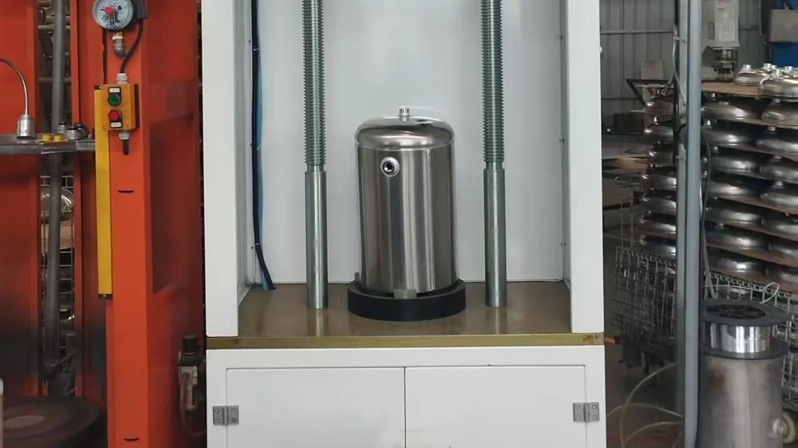
The cover photograph shows a reservoir positioned in a test fixture. It demonstrates access to test equipment, but the photograph does not prove the pressure, hold time, calibration, acceptance criterion, or result for an ordered batch. Ask for the signed report tied to the drawing revision and lot.
Where non-destructive examination is contractually required, define the method and personnel requirements. ISO 9712 covers qualification and certification for several industrial NDT methods, including leak testing, while excluding hydraulic pressure tests from its leak-testing personnel scope.
5. Define Port Geometry and Installation Interfaces
For every port, state the thread standard, size, tolerance, sealing method, angular position, stand-off height, and permissible distortion after welding. Include bracket datum positions and clearance to surrounding chassis parts. A thread gauge alone does not verify angular position or sealing-face condition.
First-article inspection should record the interfaces that can cause installation failure:
- reservoir overall length and diameter;
- bracket spacing and orientation;
- port clocking and perpendicularity;
- drain location at installed attitude;
- clearance around valves, fittings, and straps.
6. Match Surface Protection to the Contract
Specify pretreatment, coating or anodizing system, dry-film thickness where applicable, adhesion, color, masked areas, and corrosion-test requirement. ISO 9227 specifies salt-spray test apparatus and procedures, but it does not choose an exposure duration or define product acceptance for an air reservoir. Those values belong in the product specification.
Procurement Evidence Checklist
- Approved drawing and revision status
- Material certificate linked to the production batch
- First-article report covering thickness and critical interfaces
- Welding procedure and qualification evidence required by the contract
- Defined weld acceptance level and inspection record
- Leak or pressure test procedure, calibration evidence, and batch result
- Surface-treatment specification and inspection result
- Permanent marking and traceability format
- Written approval process for material or process changes
Guanda can coordinate drawing review, sample comparison, and documentation requests for aluminum reservoir sourcing. A quotation should begin with the application, drawing, pressure basis, and destination-market requirements rather than capacity alone.
Technical References
- UN Regulation No. 13 and heavy-vehicle braking — UNECE
- ISO 3834-1:2021, selection of welding quality requirements — ISO
- ISO 10042:2018, aluminum weld imperfection quality levels — ISO
- ISO 6892-1:2019, metallic material tensile testing — ISO
- ISO 9712:2021, qualification and certification of NDT personnel — ISO
- ISO 9227:2022, salt spray test procedures — ISO